
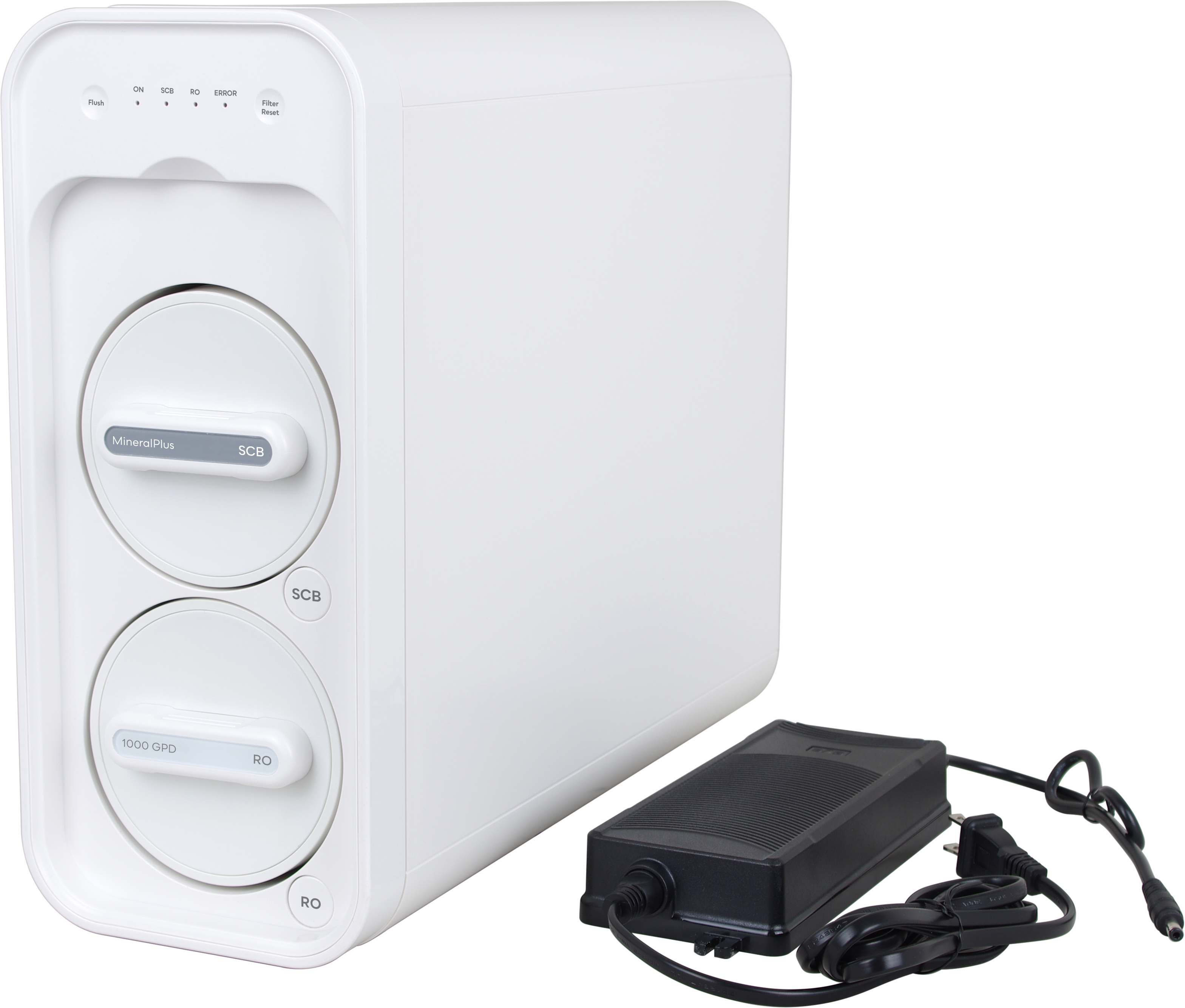
MineralPlus Tankless RO + Booster Pump, 1000 GPD
Installation Note
The installation, service, and maintenance of this equipment should be performed by a qualified professional. Speak with a local water dealer, plumber, or technician to correctly and safely install the system. Failure to follow general plumbing and electrical safety protocols, and/or failure to comply with the steps outlined in this manual could result in severe injury.
Warnings:
Electrical shock hazard! Ensure that the system is NOT connected to power during installation or servicing.
CAUTION!
- This water filtration system requires electricity to run the booster pump. Do not plug the unit in until you have read through the instructions in their entirety.
- The unit must first be connected to the cold water line and faucet, then checked thoroughly for leaks, before connecting the power transformer. Read the manual and follow all instructions.
- Do not use the power transformer if the lines are frayed or damaged, or if the transformer is damaged. Contact your dealer for a replacement.
- Children should be instructed not to touch or play with the filter system.
Notice
Do not use with water that is microbiologically unsafe or of unknown quality without adequate disinfection before or after the system.
Parts Checklist
|
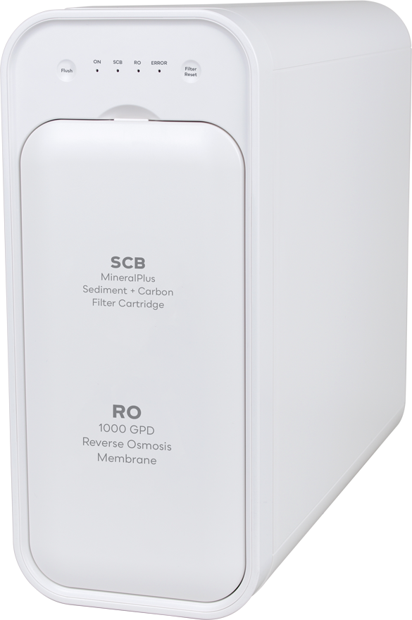
Tankless RO System + Filter Cover Plate |

|
1 SCB Filter Cartridge: 4-Stage Sediment, Carbon Block, Polishing Carbon (PPC Composite Filter), and MineralPlus media. |
|
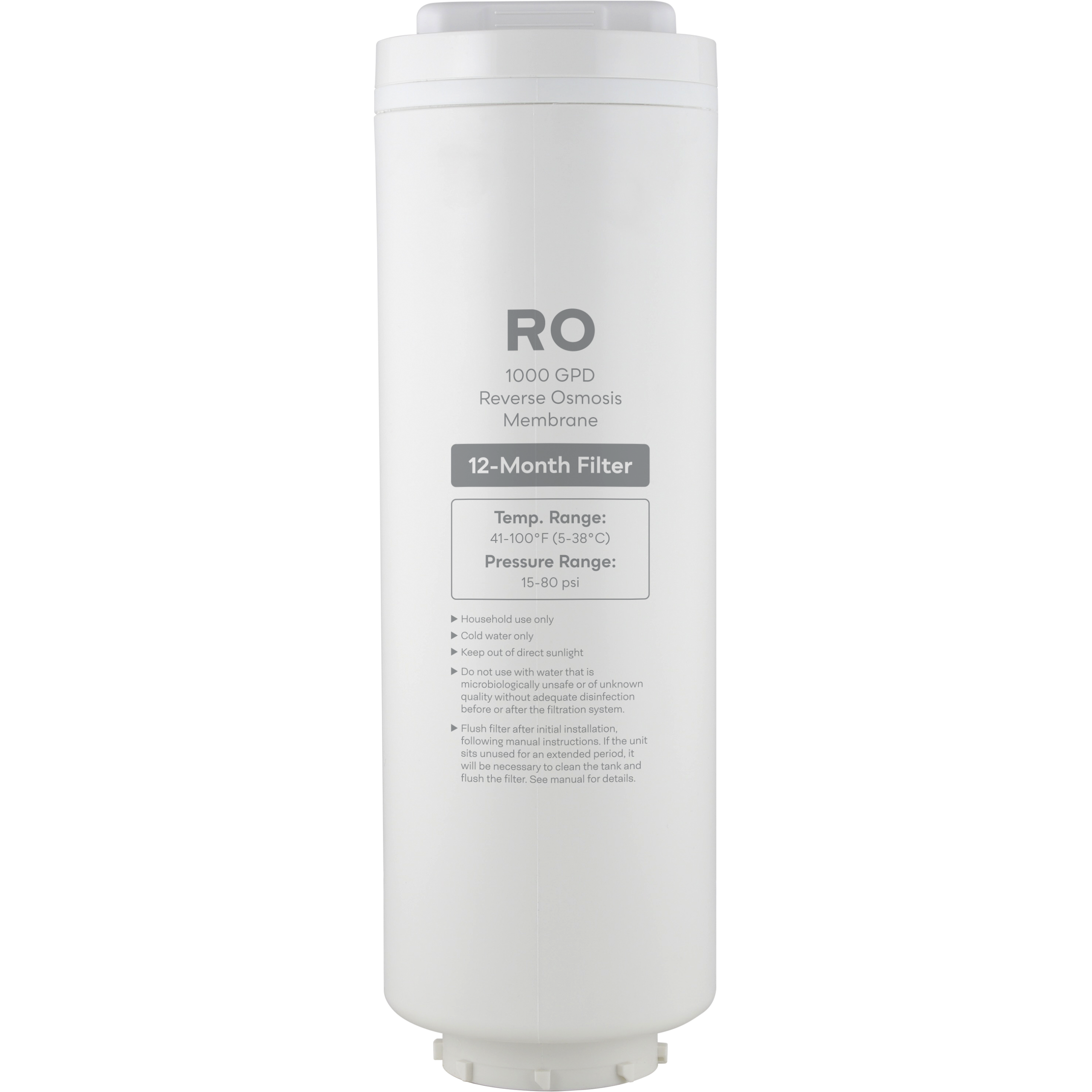
1 RO Membrane |
|
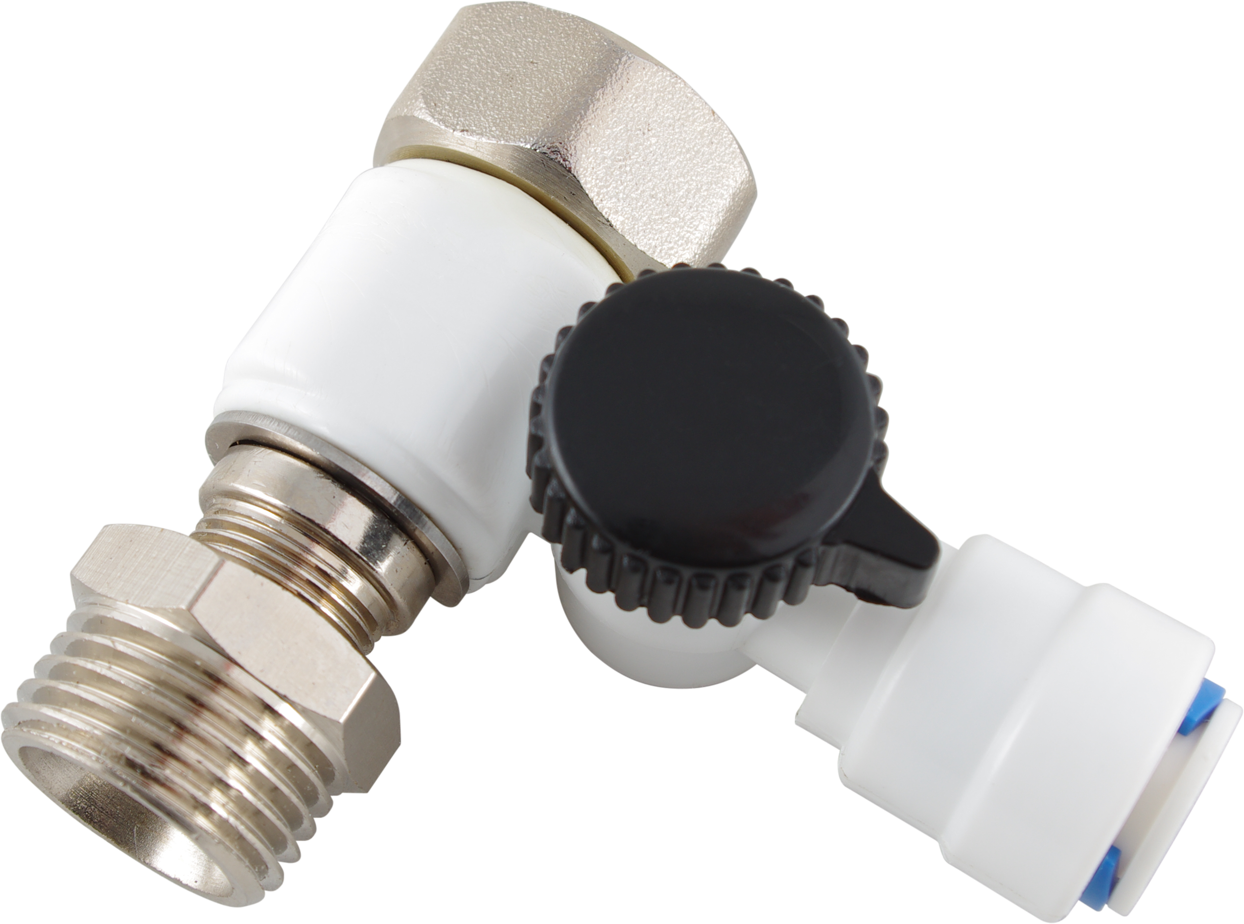
3-way Feedwater Adapter with 1/2” to 3/8" Adapter Coupler |
|
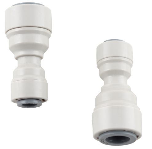
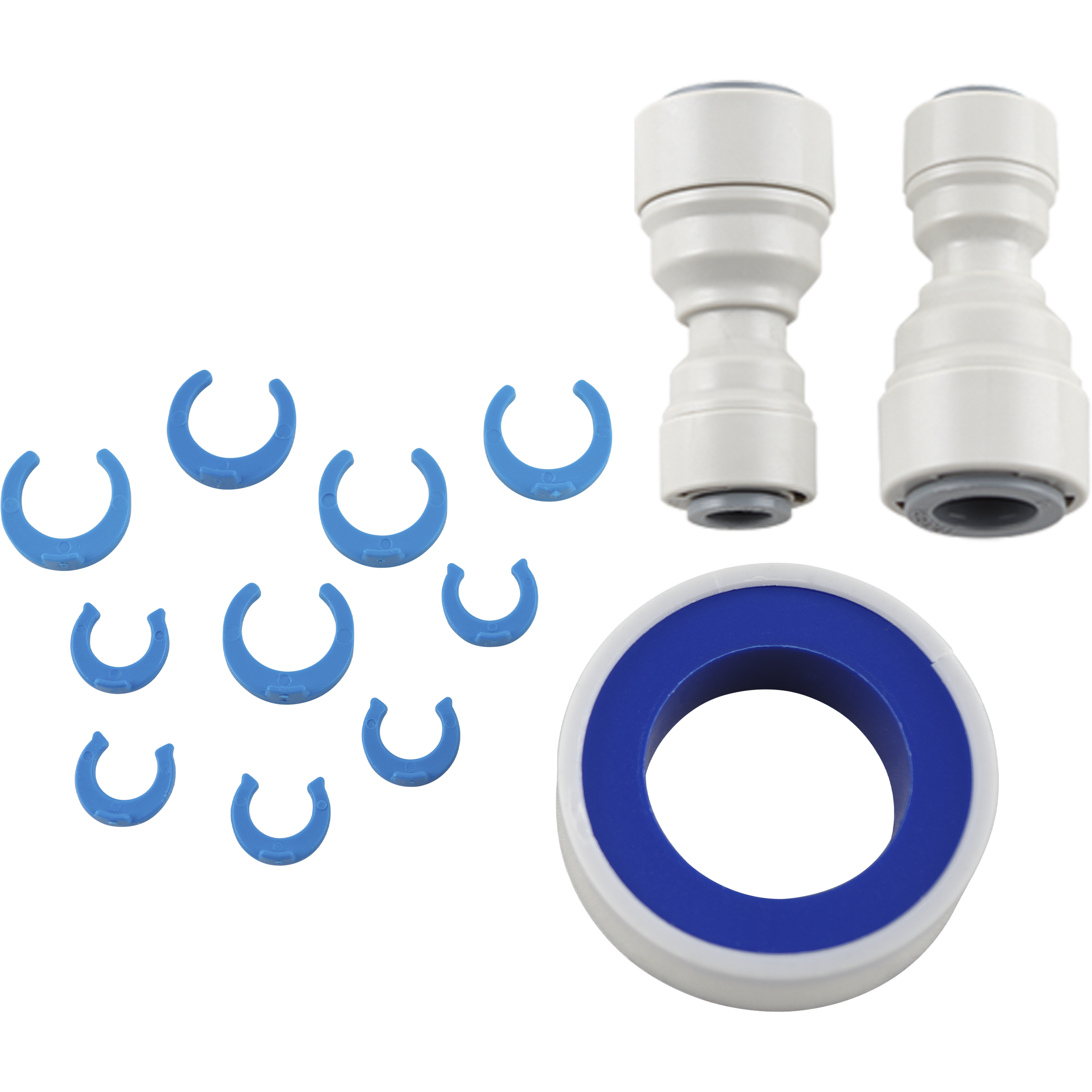
2x 1/4" Quick-Connect (QC) to 3/8” QC Adaptors |
|
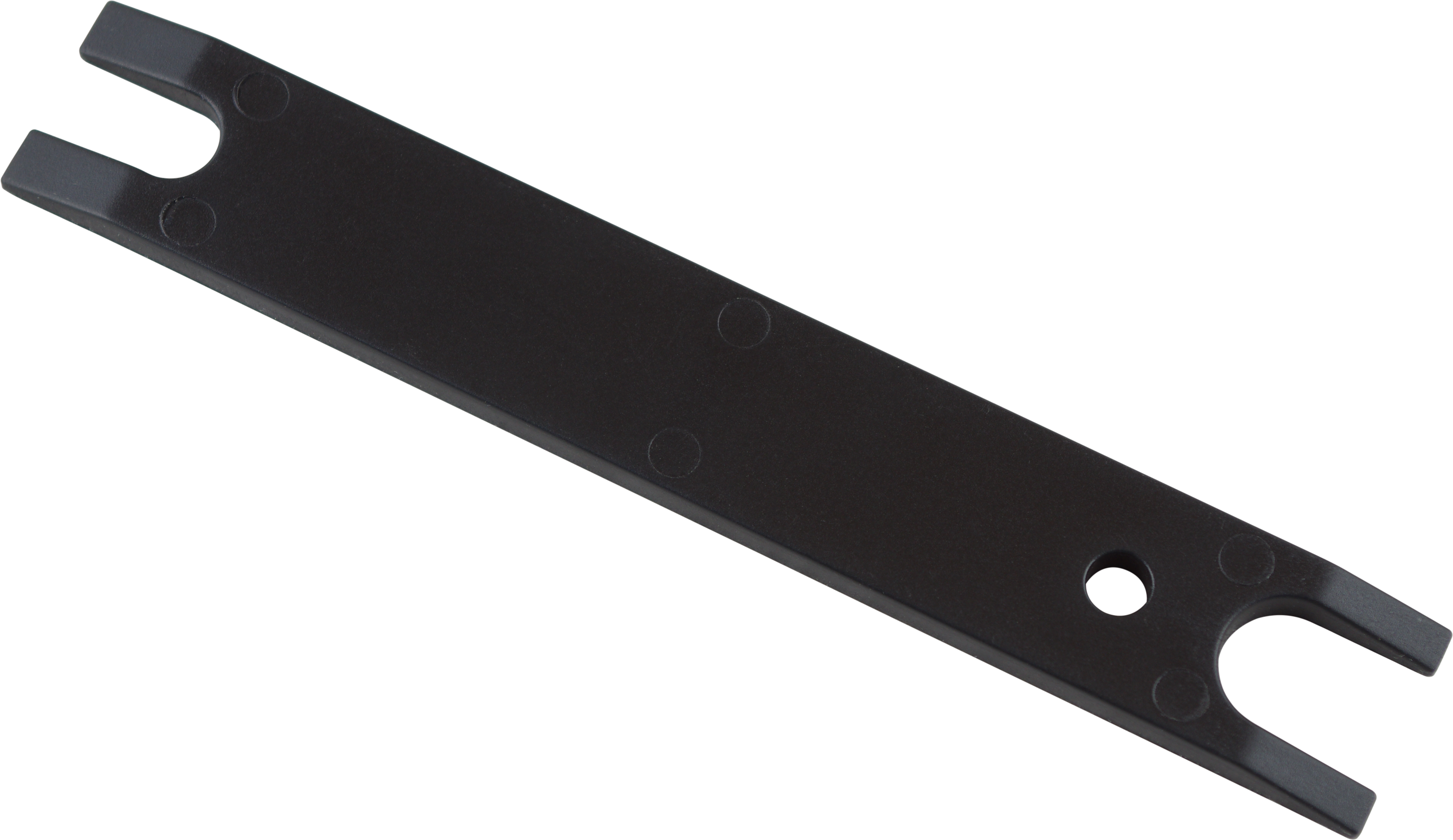
Collet Tool |
|
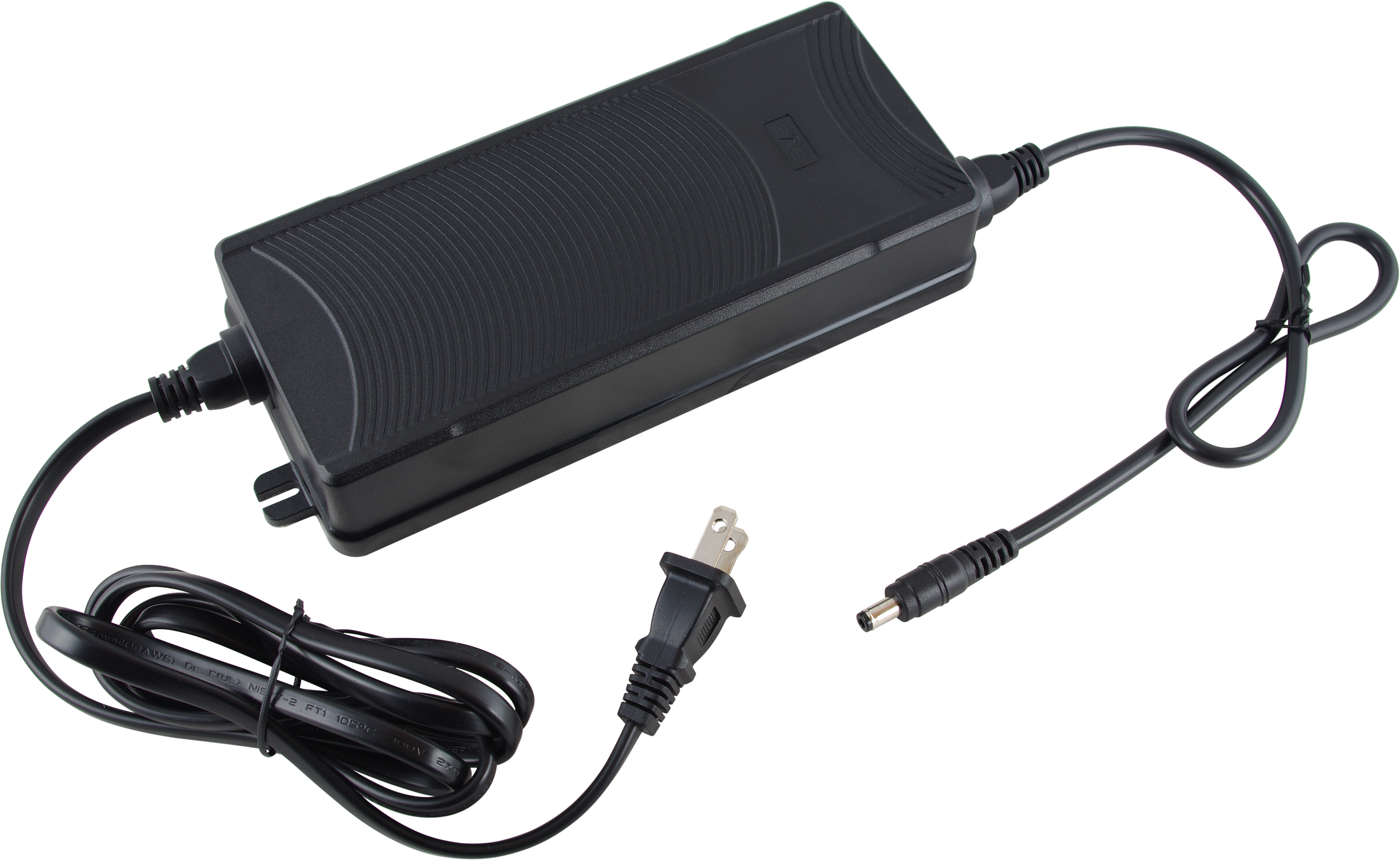
Power Transformer |
|
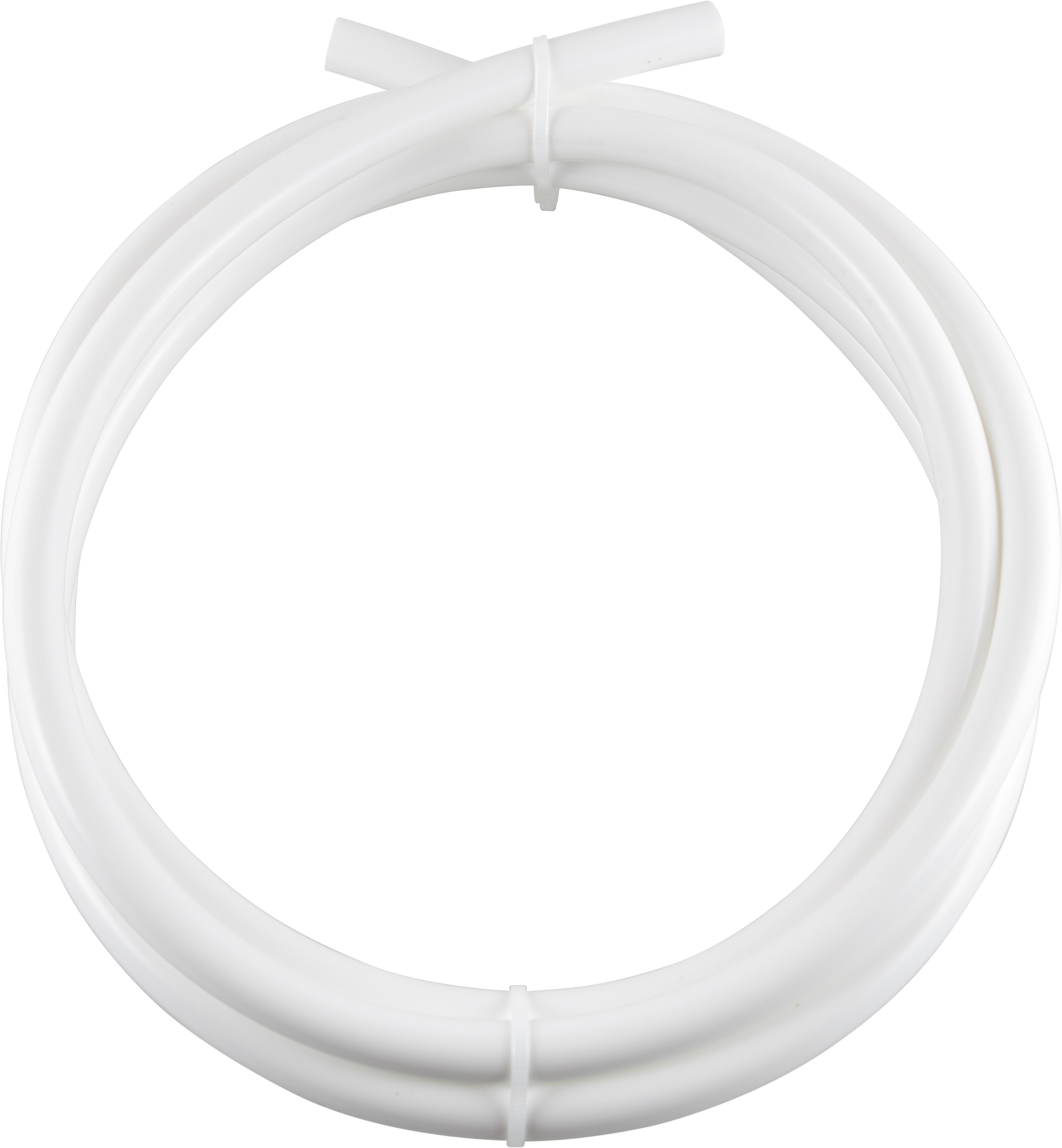
3/8” White Source Water Hose |
|
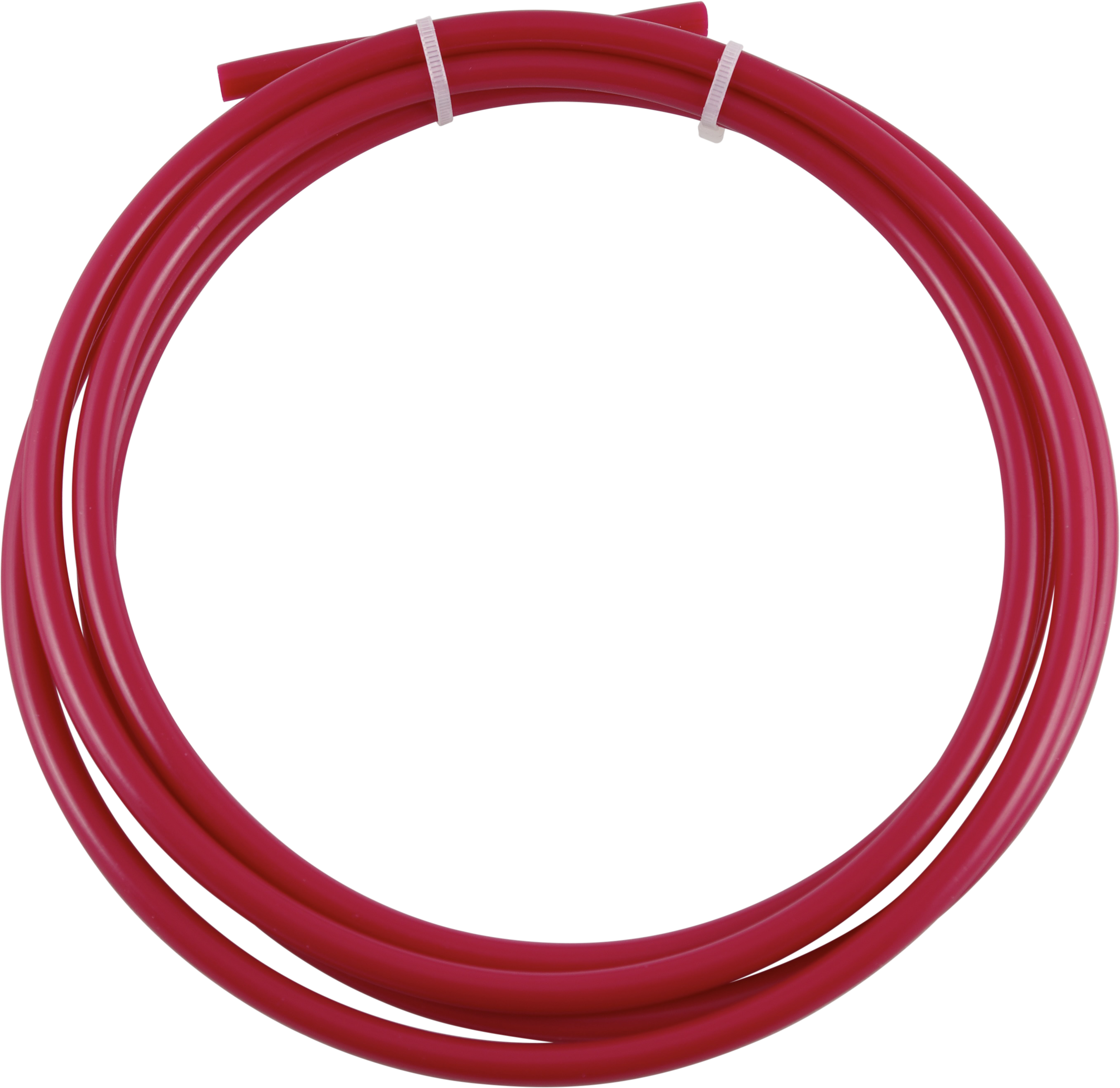
1/4” Red Wastewater Hose |
|
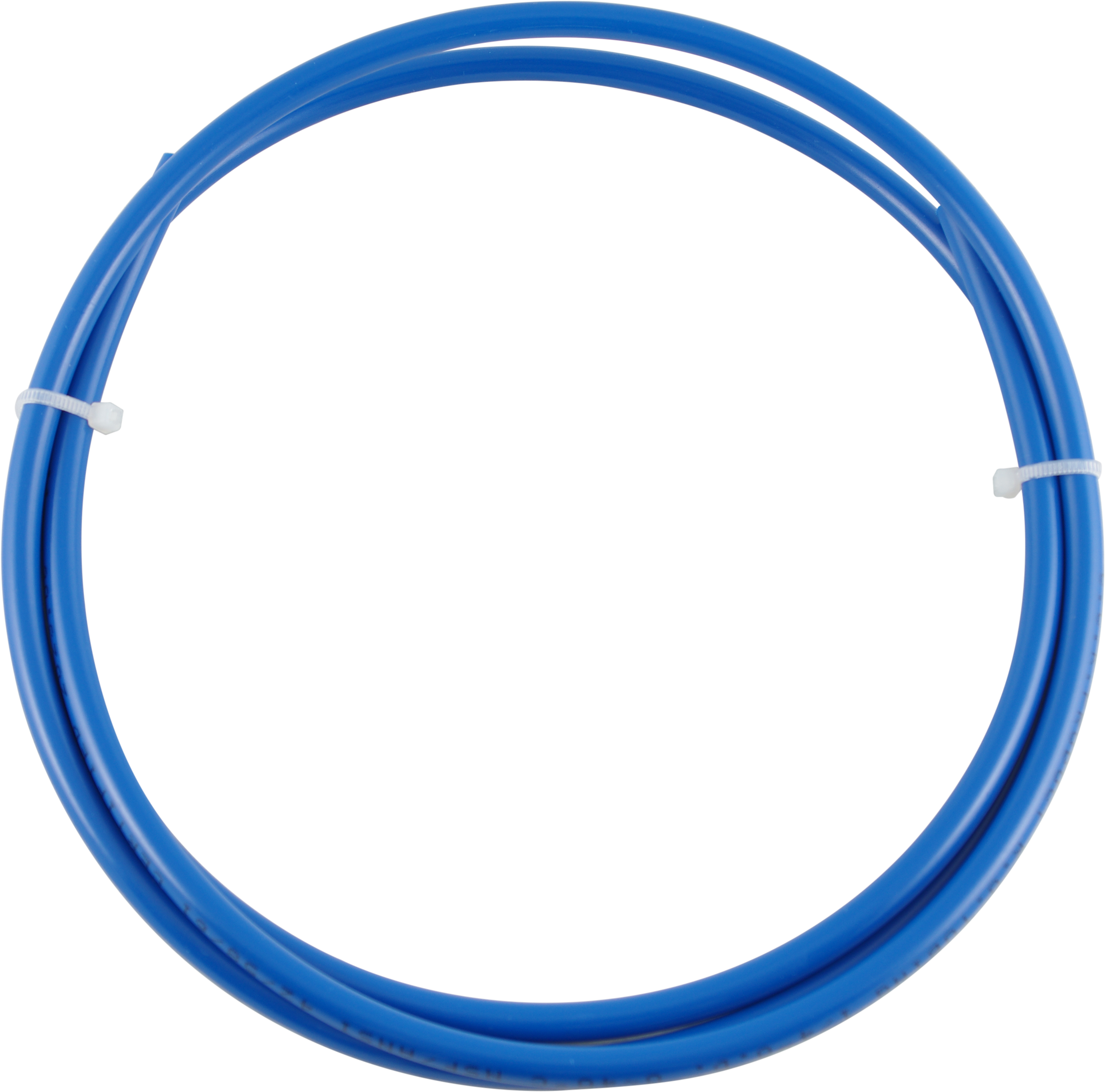
1/4” Blue Filtered Water Hose |
|
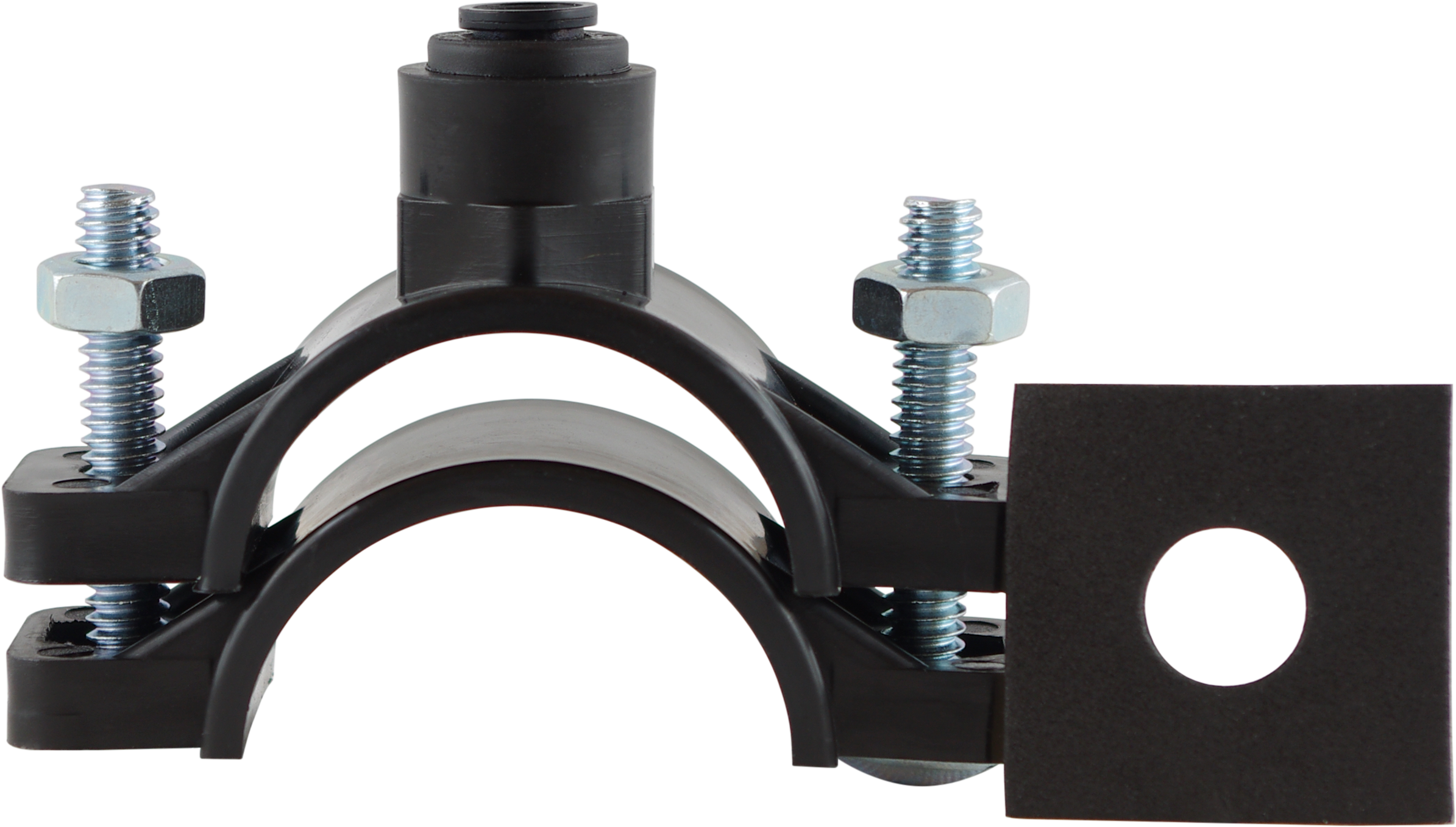
1/4” Drain Saddle |
|
Quick-Connect Fittings & Teflon Tape |
Tool List
We recommend having the following tools on hand to help with the installation process:

|
Power Drill |

|
Phillips Screwdriver |

|
1/4” Bit for Drain Saddle |

|
Adjustable Wrench |

|
Bucket or Bowl |

|
Cloths |
Advanced 5-Stage Filtration Process
Our RO1000TL tankless reverse osmosis system uses two advanced, long-lasting cartridges for fast, complete filtration and MineralPlus alkaline media for clearer, better tasting water.
| Stage | Description | Filter Life* |
|---|---|---|
| 1 | SCB: Polypropylene Sediment Filter | 12 months |
| 2 | SCB: Carbon Block Media | 12 months |
| 3 | RO: 1000 Gallons Per Day Reverse Osmosis Membrane | 12 months |
| 4 | SCB: MineralPlus Alkaline Remineralizing | 12 months |
| 5 | SCB: Polishing Carbon | 12 months |
Cartridge 1) The first cartridge (SCB) combines a polypropylene sediment filter that reduces particulate matter with a polyphosphate-impregnated carbon block to reduce chlorine, disinfectant by-products, VOCs, and offensive tastes and odors . It then finishes the water with MineralPlus remineralizing balls and a polishing carbon that further absorbs chemical impurities.
Cartridge 2) The second cartridge (RO) contains a reverse osmosis membrane that dramatically reduces total dissolved solids (TDS) down to 0.0001 micron for purer water. It can help to reduce cysts, undesirable minerals and heavy metals, PFAS, and other impurities.
*Recommended filter schedule is every 12 months or approximately 2,040 gallons of use. Filter life can vary based on usage and water quality.
Preparing for Installation
- Check the parts checklist and ensure that all parts are included and in good condition.
- Determine your installation location, ensuring that the unit is placed within reach of a power outlet, your cold water line, and your sink’s drain line for the wastewater hose connection.
- Ensure that your water pressure is within the required range. If the pressure is over 80 psi (roughly 0.55MPa), you may need to install a pressure reducing valve.
- Prepare tools, drip bucket, and drop cloths prior to beginning the installation.
Installing The FeedWater Adapter
Attention: The water supply line to the system must be from the cold water supply line only. Hot water will severely damage your system.
How to Install the Feedwater Adapter
- Turn off the cold water supply to the faucet by turning the angle stop valve completely off.
- Open the cold water sink faucet to relieve pressure from the water line.
- Prior to disconnecting the cold water line, lay down a bowl or bucket to catch any water drips. Unscrew the cold water supply line.
- Ensure the O-ring is seated inside the feed water adapter on the female end of the adapter, and the 1/2” to 3/8” metal Adapter Coupler, if using.
- When the proper connections are ready, connect both ends of the feed water adapter to the cold water supply pipe. Tighten using a wrench or pliers, but be careful not to overtighten.
- Insert the 3/8” white tubing and connect the other end to the inlet port on the RO system.
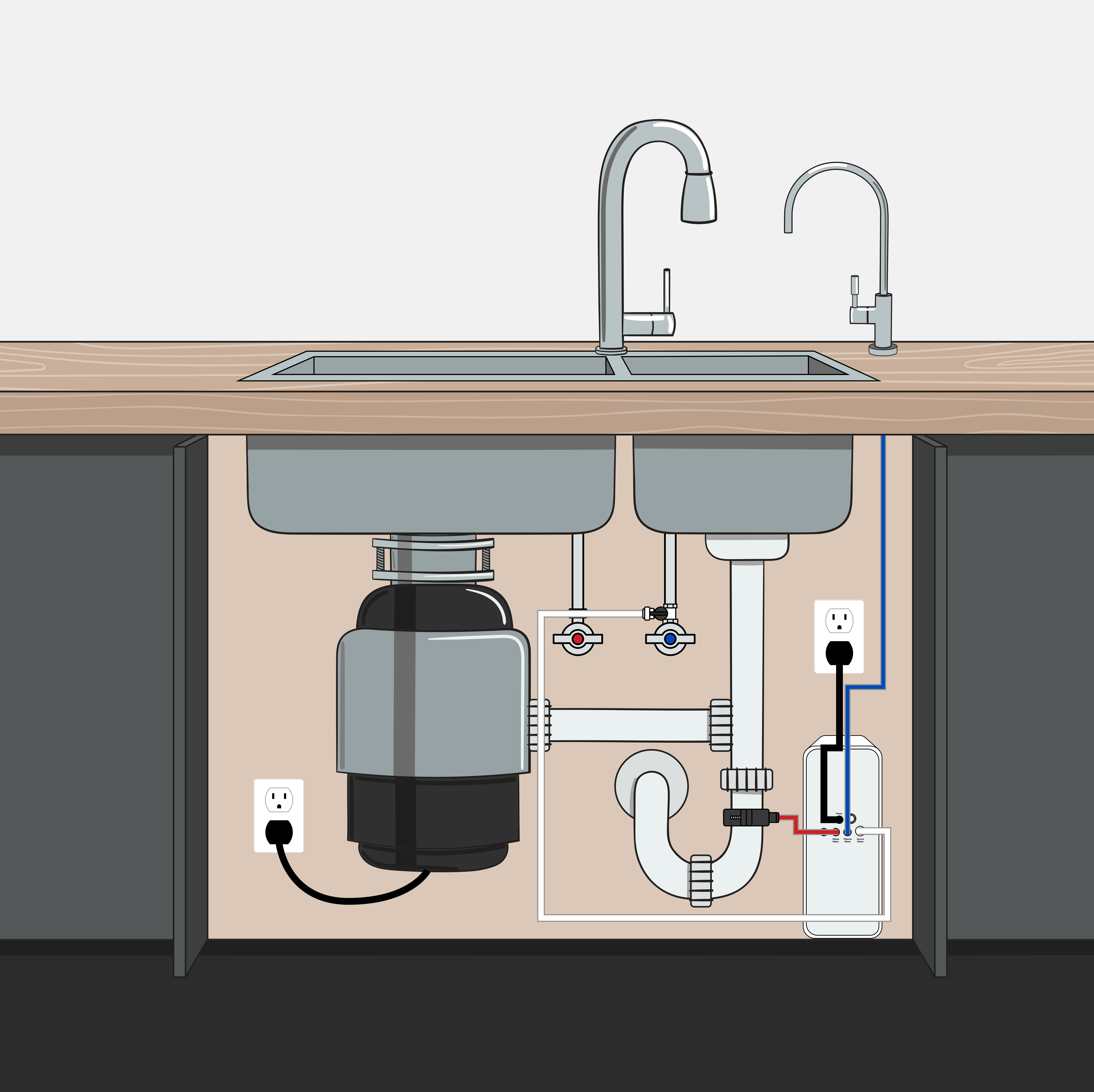
Instructions for Connecting Feedwater Adapter to RO Faucet Line
Installing The RO Faucet (Sold Separately)
- Slide the escutcheon onto the bottom of the faucet, lining up the holes on the base plate with the 3 inlet/outlet port stems on the faucet. Ensure that the escutcheon has its rubber O-ring preinstalled on the bottom.
- Insert the blue tubing and the faucet stem through the pre-drilled sink or countertop hole.
- From the underside of the sink, slide on the slotted metal washer, spacer, star washer, washer, and mounting nut. (Note: only install the thick plastic spacer if your countertop or sink is less than 1/2” thick. If 1/2” or more, spacer is not needed).
- Check the orientation of the faucet, then tighten the locking nut securely. Use a wrench to tighten. Do not overtighten fittings.
- Later, you'll connect the 1/4” blue filtered water hose to the Drinking Water Faucet port on the RO system.
- During the “Starting the System” section, you’ll open and flush the faucet with water and check for leaks.
SP-FC100 Installation Instructions

- Slide the escutcheon base of the faucet stem, and insert it into the bottom of the body of the faucet.
- Insert the faucet stem into the hole on the countertop or sink. For the next few steps, it may be easier if you have a second person hold the faucet in position above the counter.
- Underneath the counter, insert the black rubber washer in the proper position over the water lines and faucet stem, making sure to line up the pieces with the hole on the washer.
- Slide on the metal washer against the rubber washer and then slide up the plastic spacer. It may be easier to try and mount both pieces simultaneously.
- Screw the black lock washer wing nut onto the threaded faucet stem under the metal washer or optional spacer, making sure to tighten but not overtighten.
- Screw the 1/4" quick-connect union adapter onto the end of the threaded faucet stem. Be sure to tighten but not overtighten.
- Connect the blue filtered water hose for your undersink water filter system to the union adapter.
- During the “Starting the System” section, you’ll open and flush the faucet with water and check for leaks.
SP-FC210 Faucet Installation Instructions

If you wish to use your Tankless RO with an air gap faucet, you will need :
- An additional 1/4" tube to run between the unit’s Wastewater port and the faucet
- An additional 3/8" tube to run from the faucet’s drain barb fitting to the drain saddle
- A 3/8" to 1/4" quick-connect adapter to use with the included tubing and 1/4"drain saddle.
Tip: You may also use a 3/8" drain saddle (not included) instead of the quick-connect adapter.
The image below illustrates the installation of air gap faucet with an optional Leak Detector on the cabinet floor (SP-LD100).
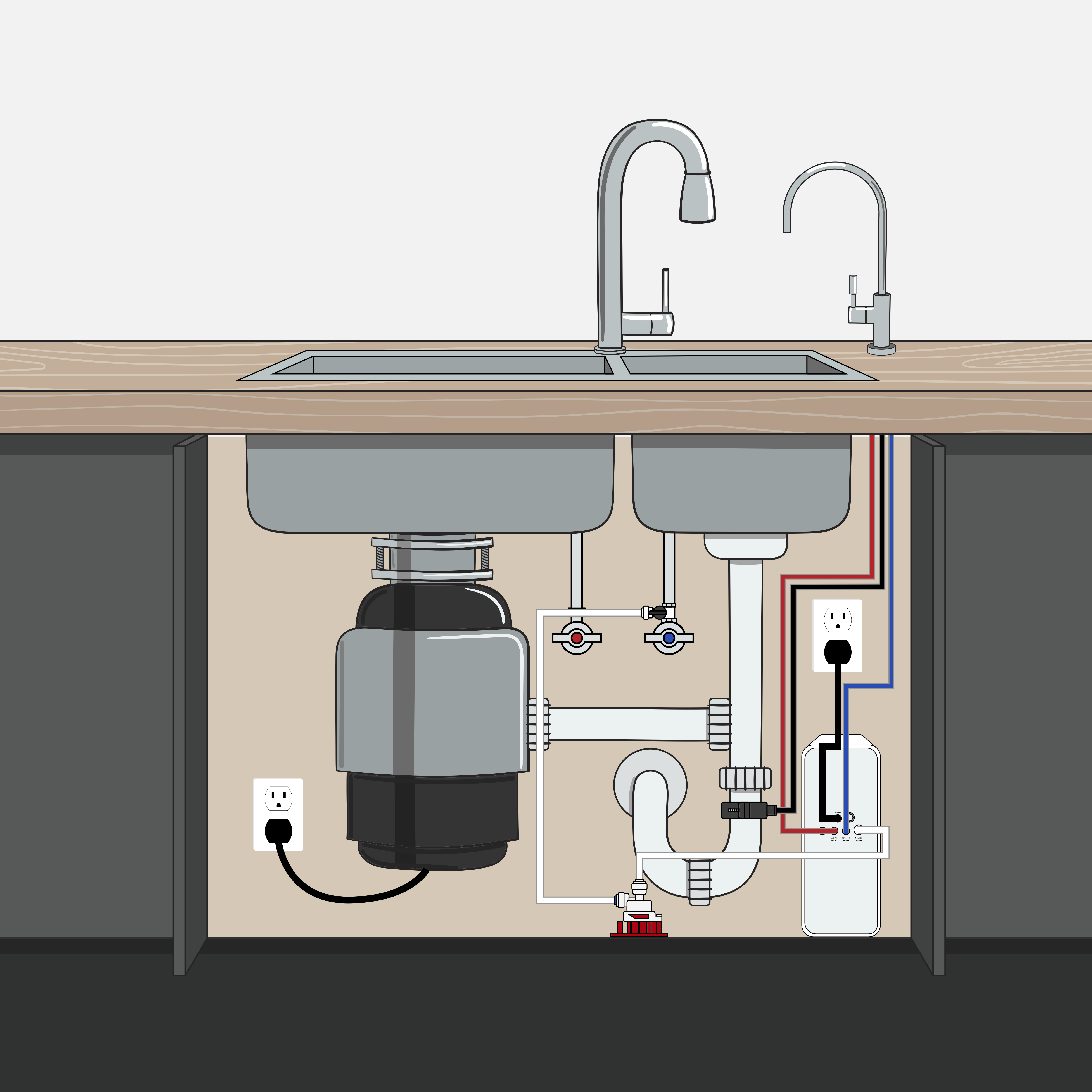
Mounting the Drain Saddle
Warning: The drain saddle creates a wastewater connection with the sink drain and is designed to fit a standard 1-1/2" outside diameter (OD) drain pipe. Drain saddles should always be installed at least 1-1/2" above the nut of the p-trap on a vertical or horizontal drain. Do not install near a garbage disposal. Take extreme caution to only drill through one side of the drain pipe.

The SP-RO1000TL ships with a 1/4” wastewater drain line. If you are using an air gap faucet with a 3/8” wastewater line, you can use a 3/8” drain saddle, or use a 1/4” to 3/8” coupler (2 included) to convert your 3/8” air gap wastewater line to a 1/4” line to fit the included drain saddle.
Locate a spot at least 1-1/2" above the nut of the p-trap on the drain pipe that is convenient for installing the drain saddle. It is recommended to install on horizontal piping to minimize dripping noise.
- The small, square, black foam gasket with a circle cut out of the middle must be applied to the inside of the drain saddle. Remove the backing and stick to the drain saddle with the cut out aligned to the drain saddle opening.
- Using the 1/4” drill bit (3/8" if you are installing a 3/8” drain saddle) drill into only one side of the drain pipe. Do not drill through both sides of the pipe.
- Assemble the drain saddle around the drain pipe and align the opening with the hole drilled in the previous step—you may use a small screwdriver or a pencil to feed through the drain saddle hole to aid with the alignment.
- Measure the 1/4” red tube from the unit to the drain saddle on the drain pipe and make a straight cut to the correct length.
- Notice: The red 1/4" drain tube to the drain saddle should be as short and straight and maintain a downward slope from the RO port (or the faucet in air gap installations) to the drain saddle to allow for proper drainage.


Tips:
- If tubing is looped, it can cause water to come out of the air gap faucet.
- Looped tubing can shorten the life expectancy of the RO membrane.
Starting the System
Ensure that the hoses are all of a sufficient length before final installation.
Install filter cartridges into the filter housing, following the designated lettering.
- Run white Source Water line from the feedwater adapter to the RO inlet port.
- Connect the red wastewater line to the Wastewater port on the RO system.
- Connect the other end of the red wastewater line to the drain saddle.
- Connect the blue filtered water line from your faucet to the blue Filtered Water port on the RO system.
WARNING: RISK OF ELECTRIC SHOCK:
Ensure that there are no visible leaks, and no sitting water near the unit. Place the power transformer somewhere safe, away from any potential leak areas. Do not allow the transformer to come into contact with water. We recommend placing the transformer on top of the tower, or wall-mounting it.
Plug the system in. Run the system, checking for leaks. If there are any leaks, shut off the system and address them before continuing.
When the system is operating correctly and with no leaks, turn on the water, and allow it to run for 30 minutes to flush the system, discarding all water during that time. Check the water and continue to flush for another 30 minutes to remove any lingering carbon fines or off tastes. Your Tankless RO filtration system is now ready for use.
Changing The Filters
When you are ready to change the filters, simply press the button next to each filter name to eject the current filter, and install the new filters. Long press “Filter Reset” to reset the indicator light. Flush system for at least 30 minutes and up to an hour after replacing filters.
Display
The display on the front machine includes indicator lights and buttons.

Flush
Press “Flush” for approximately 3 seconds to execute a flush cycle. The machine will then flush automatically for 30 seconds and the “SCB” and “RO” lights will flash during the cycle. Flush after initial installation, when replacing filters, and if you haven’t used your RO for a few days. This maintenance can help flush out accumulating impurities from stagnant water.
ON
- White light pulses slowly while filtering water
- White light is on continuously when not actively filtering
SCB
- Light is on continuously when plugged in and while filtering
- Light will turn red when it’s time to change the filter(s)
- After changing, long press “Filter Reset” to reset the indicator light
RO
- Light is on continuously when plugged in and while filtering
- Light will turn red when it’s time to change the filter(s)
- After changing, long press “Filter Reset” to reset the indicator light
ERROR
- “ON” and “ERROR” will flash together if the system is powered on but not receiving a water supply.
- “ON” and “ERROR” solid red: water pressure too high
Troubleshooting and Common Solutions
Warning Turn off the system before servicing or inspection.
| Status | Possible Cause | Solution |
|---|---|---|
| No Water Output | Air bubbles in the system | This is a normal occurrence upon system startup. The milky color will disappear with normal use in one to two weeks. |
| Is your cold water line turned on? | Turn on cold water line | |
| Is the feedwater adapter open? | Open feedwater adapter | |
| Are the filters inserted fully? | Check filters; insert until flush with unit | |
| Is the device plugged in? | Plug in device | |
| "ON" and "ERROR" Lights Flashing | No/insufficient water supply | Turn on cold water line, open feed water adapter all the way, check all hoses, ensure filters are fully inserted. |
| "ON" and "ERROR" Lights Solid Red | Home water pressure is too high | Install a pressure reducer valve to 60psi or less |
| Slow flow rate | Are any hoses bent, pinched, twisted, or kinked? | Straighten hoses |
| Are the cold water lines and feedwater adapter fully open? | Ensure that both are fully open | |
| Do the filters need to be changed? | Change filters | |
| Unit is running non-stop | There is a problem with the automatic shut-off valve, or the fittings. | Close the feedwater adapter giving water to the unit, and unplug the unit. Contact your water dealer, plumber, or installer for servicing. |
| The water smells strange | This can happen after a period of extended disuse. | Flush the membrane for anywhere from 20 minutes to an hour, or until water tastes and smells fresh. |
| Leaking at hose connections | This can happen if:
|
Ensure first that the hose was cut at a flush 90 degree angle, with a razor blade or angle cutters. If the hose is bent, bowed, or pinched, it will leak. Then firmly push in the hose, until fully and properly seated. Tug gently to ensure proper seating. |
Product Parameters
Description RO Water Purifier
| Rated Voltage/Frequence: | 110V/60Hz |
| Rated Power: | 120W |
| Inlet Water Pressure: | 15–80 psi |
| Source Water: | Tap water |
| Filtered Water Flow Rate: | 0.68 gal/min |
| Usable Water Temp. Range: | 41-100°F (5~38°C) |
| Room Temp. Range: | 39-104°F (4~40°C) |
Manual Warnings
When using this electrical appliance, always follow basic safety precautions to reduce the risk of fire, electrical shock, and/or bodily harm to persons or damage to the device, including the following:
- Read all instructions on the system and in the manual thoroughly before setting the device up for the first time.
- Only connect to a grounded outlet.
- Do not touch hot surfaces.
- To protect against electric shock, fire, and possible injury to persons and/or system damage, do not immerse the machine, its individual parts, or its cord or plug in water or any other liquid.
- Closely monitor children around the device. Young children should not use the device themselves.
- Unplug the device during periods of extended disuse, and before cleaning the device or changing the filters. Allow the device to cool before putting on or taking off parts, and before cleaning.
- Do not plug in or attempt to operate if it is visibly cracked or damaged, or if it has a damaged cord or plug. Contact your supplier immediately in such a case.
- Do not use outdoors.
- Do not store inflammable and volatile substances near the system.
- To disconnect, remove plug from outlet. Pull plug from head, not cord; do not yank cord.
- Do not use appliance for other than intended use.
- For household/indoor use only.